

This voltage setpoint calculator is part of a series of design calculators for switching DC power supply feedback compensators. It allows you to input the desired setpoint voltage and the Vref voltage, which is typically determined by a Zener diode. In practical applications, the resistors used in the voltage setpoint circuit are 1% tolerance or better accuracy. So this calculator outputs the top ten best combinations of resistors to achieve your desired voltage setpoint. Each result shows what the actual voltage setpoint should be, as well as the error percentage from your desired setting.
To use this calculator, enter your desired setpoint voltage and the Vref voltage of the regulating Zener diode. The top ten results will display automatically.
Compensator Voltage Setpoint Formula
The formula below solves the setpoint voltage when you already have a Vref voltage and a pair of resistors. Because this calculator solves an optimization problem, there is no simple formula to give you the best answer for resistors' combination. This calculator takes every possible combination of 1% tolerance resistors and solves each of them for the resulting voltage setpoint. Then the calculator gives you the top ten results of all possible combinations that best match your desired voltage setpoint. Frankly, the fact that you will need to guess and check to find the best resistor combinations is why such a calculator is useful.
Compensator Voltage Setpoint Formula:where:
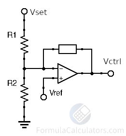
• Vset = Setpoint Voltage
• Vref = Reference Voltage • R1 = Upper Resistor • R2 = Lower Resistor
Voltage Setpoint Solution Examples:
Generally speaking, the goal of performing these calculations will be to help you find the optimal set of resistors that will achieve the desired setpoint voltage, or you will want to determine what the setpoint voltage will be given a set of resistors. We will go through a few practical examples that allow you to get a feel for selecting compensator setpoint resistors.
Example #1: Determine the Setpoint
In this first example, we will assume that you are given setpoint resistors and the Vref voltage. You will use the setpoint formula to check what the setpoint voltage will be.
The Vref voltage set by a Zener diode is 1.25 Volts, the R1 resistor is 10.3kΩ, and the R2 resistor is 3.4kΩ.
We use the formula provided above and enter our known variables to solve for Vset.
This was pretty straightforward because we only had to plug the values we were given into the setpoint formula and solve.
The solution is that when you have a Vref voltage of 1.25 Volts, a 10.3kΩ R1 resistor, and a 3.4kΩ R2 resistor, the setpoint voltage is 5 Volts.
Example #2: Finding a Good Match
In this next example, we will assume that you have the desired setpoint voltage of 6 Volts in mind and are given a Vref voltage of 1.25 Volts. You realize that there are a lot of combinations of resistors that you could try to get this voltage, so you decide that because you have a surplus of 1kΩ high precision resistors, and would like to try using one for the R2 resistor.
You want to find the closest standard R1 resistor value that will get you close to a 6 Volt setpoint. And once you find it, you want to go back and check what the setpoint voltage will actually be if you use that combination of resistors.
The first step is to use some algebra on the provided formula to solve for R1.
This gives us a new formula to solve for R1 below.
Plugging in the desired 6 Volt setpoint, the 1.25 Volt Vref from the Zener diode, and the 1kΩ R2 resistor that we want to try, we get the following.
So if we use a 3.8kΩ resistor for R1, the setpoint will be exactly 6 Volts. This is great, but the only problem is that 3.8kΩ is not a common 1% or better tolerance resistor value. The closest standard resistor value is 3.83kΩ which is a little bit off. Because of this, we should check what the setpoint voltage will really be if we use the closest standard value of 3.83kΩ for the R1 resistor. We will use Vset Setpoint formula below to solve for our selected resistors and Vref voltage.
So you see that because we are limited to real-world standard resistor values, we can get close to our desired setpoint using this method of choosing one resistor value and solving for the closest matching resistor. If your specification allows for the setpoint to be off by this amount, then this is a valid solution.
You can use this process to try other combinations of resistors, and find better matches. But this is where using the calculator on this page can save you a lot of time. Go ahead and try entering a setpoint of 6 Volts and a Vref of 1.25 Volts into the calculator, and you will see that there is no exact match using standard resistor values. However, the solution that we just found in this example doesn't even make it into the top ten best answers.